Mastering the Spatial Dimension: The Art of Testing MIMO, Beamforming, and Multipath
- Feb 3
- 5 min read
In traditional wireless communications, we have always fought against the Multipath Effect. Signals reflecting off buildings and arriving at the receiver at different times caused self-interference (fading), which was once the nightmare of RF engineers.
However, modern communication technologies (LTE, 5G, Wi-Fi 6/7) have achieved a spectacular reversal of physics: We no longer try to eliminate multipath; we exploit it.
This is the essence of MIMO (Multiple-Input Multiple-Output). By simultaneously using multiple antennas at both the transmitter and receiver, we have unlocked a completely new dimension of communication—the Spatial Dimension.
This introduces two concepts that are often confused but operate on entirely different physical mechanisms: Beamforming and Spatial Multiplexing.

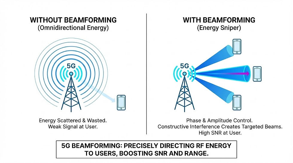
Concept 1: Beamforming — The Energy Sniper
Beamforming is relatively intuitive. Its goal is to improve Signal-to-Noise Ratio (SNR)—making the signal "heard" more clearly and travel further.
Imagine a 5G base station with 64 antennas.
Without Beamforming: It’s like turning on a lightbulb. Energy scatters in all directions, with most of it wasted in space where no users exist.
With Beamforming: The base station precisely controls the "phase" and "amplitude" of the signal emitted by each of the 64 antennas. Through the principle of Constructive Interference, these electromagnetic waves add up and reinforce each other in a specific direction while canceling each other out in others.
The result is a high-energy "RF Beam" precisely aimed at the user. This not only compensates for high-frequency path loss but also reduces interference for users in other directions.
The Test Challenge: This requires us to verify in an OTA chamber whether the beam "points accurately" and whether the beam shape (main lobe width, sidelobe levels) matches mathematical models.
Concept 2: Spatial Multiplexing — Channels to Parallel Universes
If Beamforming is "making the pipe wider" (improving SNR), then MIMO Spatial Multiplexing is "laying multiple pipes" (increasing capacity). This is the magic of MIMO.
In a SISO (Single-Input Single-Output) system, only one data stream can be transmitted at the same time and frequency. But in a 2x2 MIMO system, we can transmit two completely different data streams (Stream 1 and Stream 2) at the same time and same frequency.
This sounds counter-intuitive: If two antennas shout on the same frequency simultaneously, doesn't the receiver just hear a jumbled mess of noise?

Decoding: Using "Difference" to Separate Signals
The reason the receiver can distinguish these two streams relies entirely on the differences in spatial paths.
Stream 1 from Antenna A arrives at the receive antenna via a direct Line-of-Sight path.
Stream 2 from Antenna B arrives at the receive antenna after reflecting off a wall.
Because the paths are different, these two signals arrive at the receive antenna array with different phase differences and amplitude differences. The powerful mathematical unit inside the receiver solves a system of simultaneous equations (matrix operations), using these differences to "untangle" the mixed signals and restore them into two independent data streams.

Key Conclusion: Spatial Multiplexing can double data throughput (2x2 MIMO doubles it, 4x4 quadruples it) without adding any extra bandwidth or power. This is the holy grail of spectral efficiency.
The Physical Limit: Matrix Rank and Condition Number
Since MIMO is so great, why can't we just use infinite antennas (e.g., 100x100 MIMO) to get infinite internet speed?
Because the physical environment limits the "solvability" of the equations.
Matrix Rank: The Effective Dimension of the Channel
Rank represents the maximum number of "independent data streams" the current wireless environment can support.
Rank 1: The environment is too simple (e.g., only one direct Line-of-Sight path). The signals received by all antennas are identical and indistinguishable. The system automatically falls back to single-stream transmission (Diversity Mode), improving reliability but not speed.
Rank 4: The environment is very complex (Rich Scattering), with plenty of independent reflection paths. The receiver can easily distinguish 4 streams, quadrupling the speed.

Condition Number: The Health Check of MIMO
For test engineers, the Condition Number is the core mathematical metric (in dB) for evaluating MIMO channel quality.
It describes how difficult it is to "invert" the channel matrix. In layman's terms, it measures how "hard to distinguish" the two data streams are spatially.
Low Condition Number (e.g., 0-5 dB): The two paths are vastly different (e.g., one from the left, one from the right). Mathematically easy to solve. MIMO performance is excellent; streams are clear.
High Condition Number (e.g., > 20 dB): The two paths are very similar (e.g., both from the same direction with tiny angular difference). Mathematically hard to solve; the calculation amplifies noise. MIMO performance drops drastically, and the system may be forced to lower the Rank.
Test Insight: When testing MIMO performance in the lab, if throughput is low, the first thing to check is the Channel Condition Number. If the test setup (e.g., antenna placement) causes a high condition number, no chip in the world can achieve high speeds.

The Test Paradox: The Choice Between Chamber and Reverb
MIMO and Beamforming have diametrically opposed requirements for the test environment, creating a huge challenge for lab setup.
1. Beamforming Needs "Silence" (Anechoic Chamber)
To verify beam pointing accuracy, we need an environment without reflections (Anechoic Chamber). Any wall reflection will distort our measurement of the beam shape.
2. MIMO Multiplexing Needs "Noise" (Rich Scattering)
To verify MIMO throughput (e.g., 4x4 download speed), we need an environment full of reflections! If you test 4x4 MIMO in a perfect anechoic chamber, due to the lack of reflected paths (Rank = 1), the channel matrix between phone and base station becomes highly correlated (High Condition Number). The MIMO mechanism fails, and throughput collapses to SISO levels.
This is a physical paradox: An environment that is too clean kills MIMO; an environment that is too messy kills Beamforming.

The Solution: MPAC and Channel Emulators
To reproduce "controlled chaos" in the lab, the industry uses advanced MPAC (Multi-Probe Anechoic Chamber) systems.
We place a ring of probe antennas (e.g., 16 probes) around the DUT in a non-reflective chamber.
These probes are connected to an expensive Channel Emulator.
The Channel Emulator artificially creates delays, attenuations, and phase shifts to simulate effects like "this signal reflected off a wall" or "that signal bounced off the ground."
In this way, we electronically synthesize a mathematically "Rich Scattering" virtual city environment inside a physically "quiet" chamber. This allows test engineers to freely adjust the Condition Number and test the receiver's demodulation algorithms at the very edge of their limits.

Conclusion: From Scalar to Vector to Space
The history of RF testing is a history of dimensional expansion.
Early days, we focused on Scalar: Is power high enough? Is frequency correct?
Later, we focused on Vector: Is EVM good? Is phase accurate?
Now, we must master Space: Where is the beam pointing? How many independent paths does the environment have?

MIMO and Beamforming technologies prove that communication is not just electron flow on a circuit board, but a geometric dance of electromagnetic waves in 3D physical space. As test engineers, we must possess this "spatial imagination," understanding the delicate balance between direct and reflected paths, Rank and Condition Number, to build the digital highways to the future in the invisible air.


Comments