5G NTN Technical Deep Dive: Architecture, RF Challenges & Protocol Evolution
- Jan 23
- 5 min read
Updated: Jan 23
With the finalization of 3GPP Release 17, 5G Non-Terrestrial Networks (NTN) have officially heralded the era of "three-dimensional connectivity." This article provides a comprehensive technical analysis of the NTN infrastructure, dissecting the evolution from Transparent to Regenerative payloads. We conduct a deep dive into the physical and protocol layer solutions designed to mitigate Doppler shifts, extreme Round-Trip Time (RTT), and complex channel fading in LEO/GEO constellations, paving the path toward 6G unified networks.

The Vertical Expansion of 5G
For decades, cellular networks have been constrained to the two-dimensional surface of the Earth. While Terrestrial Networks (TN) cover the majority of the global population, they span only a fraction of the planet's landmass and oceans. 5G NTN represents a paradigm shift, integrating Satellite Communications (SatCom) directly into the 3GPP ecosystem to achieve ubiquitous global coverage.
The impetus for NTN arises from the convergence of two massive ecosystems: the telecommunications sector seeking to close the digital divide (rural, maritime, airborne connectivity) and the "NewSpace" aerospace sector deploying mega-constellations of Low Earth Orbit (LEO) satellites. This integration requires addressing fundamental physics challenges that do not exist in terrestrial 5G.
Architectural Evolution of 5G NTN
Under 3GPP specifications, NTN architecture is not monolithic. It adapts based on the satellite's processing capabilities, defining how the Next-Generation Radio Access Network (NG-RAN) is split between space and ground.
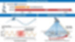
Transparent Architecture (Bent-Pipe)
This is the baseline for 3GPP Release 17. The satellite acts strictly as an analog RF repeater in space.
Signal Flow: The 5G NR signal from the User Equipment (UE) traverses the Service Link to the satellite. The satellite performs frequency conversion (uplink to downlink frequencies), filtering, and amplification, then relays the signal via the Feeder Link to a terrestrial NTN Gateway, which connects to the gNB.
Protocol Termination: Crucially, the 5G Uu radio interface terminates at the terrestrial gNB, not the satellite. Consequently, the radio loop latency includes the entire path: UE ↔ Satellite ↔ Gateway ↔ gNB
Implication: This architecture minimizes satellite SWaP (Size, Weight, and Power) and complexity, allowing legacy bent-pipe fleets to support 5G NTN via ground station upgrades.

Regenerative Architecture (On-Board Processing)
Targeted for Release 18+ and 6G, this architecture moves intelligence into orbit.
Functional Split: The satellite houses part or all of the gNB functionality.
Full gNB on Satellite: The satellite contains both Centralized Unit (CU) and Distributed Unit (DU), connecting directly to the 5G Core (5GC) on the ground.
gNB-DU on Satellite: The satellite hosts the DU (PHY/MAC/RLC layers), while the CU remains terrestrial.
Technical Advantages:
Latency Reduction: By terminating the Uu interface at the satellite, latency-sensitive loops like HARQ are handled in orbit, drastically reducing RTT.
Inter-Satellite Links (ISL): Regenerative payloads enable mesh networking in space, allowing data routing between satellites (e.g., in a "+grid" Walker constellation) without bouncing back to earth at every hop.

Orbital Dynamics and Channel Propagation
The transition from static towers to orbiting nodes introduces dynamic variables that disrupt traditional cellular assumptions.
Round-Trip Time (RTT) and Differential Delay
The Scale: While terrestrial 5G deals in microseconds, NTN deals in milliseconds. GEO RTT can exceed 544 ms; LEO RTT ranges from 20 to 50 ms.
Time-Variance: In LEO, the distance between the satellite and UE changes continuously, causing the RTT to fluctuate dynamically during a single session.
Differential Delay: Within a single satellite beam footprint (which can span hundreds of kilometers), the delay difference between a user at the beam center (nadir) and the beam edge can exceed 10 ms. This impacts the gNB’s ability to schedule uplink slots and requires robust buffer management.
Massive Doppler Shift
LEO satellites orbit at velocities around 7.6 km/s. This imparts a massive Doppler shift on the carrier frequency.
Magnitude: At 30 GHz (Ka-band), Doppler shift can reach ±720 kHz; at 2 GHz (S-band), it approaches ±48 kHz. Standard OFDM subcarrier spacing cannot tolerate this unassisted.
Doppler Rate: The rate of change of the frequency shift is highest when the satellite is at high elevation angles relative to the user.
Compensation Strategy: 3GPP mandates UE-side pre-compensation. The UE must utilize on-board GNSS to determine its location and calculate the relative velocity vector using broadcast Ephemeris data (orbital parameters). The UE intentionally shifts its uplink frequency so that the signal arrives at the satellite "pre-corrected" to the nominal frequency.

RF Physical Layer Challenges
The Link Budget Crisis
Free Space Path Loss (FSPL) is the dominant adversary.
The Physics: FSPL increases with the square of the distance. Bridging 600 km (LEO) or 36,000 km (GEO) requires significant gain.
G/T Ratio: The Gain-to-Noise-Temperature ratio (G/T) is the critical Figure of Merit (FoM). High-gain Phased Array Antennas are essential on both the satellite and the UE (especially for VSATs) to close the link.
Atmospheric Impairments: Beyond FSPL, the link budget must account for Scintillation (rapid fluctuations in refractive index) and Rain Fading (critical for Ka-band operation).

Polarization and Faraday Rotation
As signals traverse the ionosphere, the Earth's magnetic field interacts with the ionized medium, causing the polarization plane of linear signals to rotate (Faraday Rotation).
Impact: At lower frequencies (L/S-band), this can cause severe polarization mismatch loss if linear polarization is used.
Solution: NTN predominantly utilizes Circular Polarization (LHCP/RHCP). Circular polarization is immune to rotation orientation, preventing the potential 3 dB (or infinite cross-pol) loss associated with linear polarization misalignment.

Channel Modeling (TDL/CDL)
Standard terrestrial models (like Urban Micro) do not apply. NTN channels are characterized by:
Line of Sight (LOS): High probability of LOS, resulting in low angular spread (planar waves).
Clustered Delay Line (CDL): 3GPP TR 38.811 defines CDL models that incorporate elevation-dependent parameters. Low elevation angles suffer higher shadowing (Clutter Loss) and atmospheric attenuation.

Protocol Stack Adaptations
To accommodate the physics of space, the 5G protocol stack required surgical modifications.
HARQ (Hybrid Automatic Repeat Request)
Legacy Stop-and-Wait HARQ is inefficient in high-latency environments.
Process Expansion: 3GPP increased the number of HARQ processes from 16 to 32 to keep the data pipe full while waiting for acknowledgments.
Disabling HARQ: For specific services or extreme latencies, HARQ can be disabled, relying on RLC-layer ARQ or Blind Retransmissions to ensure reliability without the latency penalty.
Timing Advance (TA) Enhancements
Traditional RACH-based TA estimation fails because the propagation delay exceeds the random access response window.
Mechanism: TA is now a sum of Common TA (broadcast by the network covering the Feeder Link delay) and UE-Specific TA (calculated autonomously by the UE using GNSS and Satellite Ephemeris).
K_offset: A new scheduling parameter, K_offset, is introduced to delay uplink transmission slots, ensuring that the gNB receives signals at the correct frame alignment despite the massive RTT.
Mobility Management
Moving Cells: In LEO, cells move across the ground. This forces UEs to perform frequent handovers even if stationary.
Earth-Fixed Tracking Areas: To prevent signaling storms from millions of UEs performing Tracking Area Updates (TAU) constantly, NTN uses Earth-Fixed Tracking Areas. The satellite broadcasts different Tracking Area Codes (TAC) depending on which geographical region it is currently serving, decoupling the satellite ID from the geographical ID.
Conclusion and Future Outlook
5G NTN is a foundational technology that unifies the terrestrial and aerospace domains. Moving from Release 17’s transparent architecture to Release 18’s enhancements in coverage and mobility—and looking toward 6G’s fully regenerative, autonomous organic networks—the technical trajectory is clear. Success in this domain requires mastering the intricate dance of orbital mechanics, precise time-frequency synchronization, and advanced channel modeling. For engineers, the challenge shifts from managing static cell towers to orchestrating a dynamic, high-velocity mesh of nodes in the sky.